Rank: Member
Groups: Registered
Joined: 2/10/2011(UTC)
Posts: 8
|
I need a detailed diagram or picture showing me how to connect the terminals of the replacement power cord I brought for my GE chest freezer.
The power cord part number is WR23X10458
I think I have it connected right but I ain't plugging it in until I'm certain everything's where it needs to be at! :eek:
Thanks in advance!
|
|
|
|
|
|
Rank: Member
Groups: Registered
Joined: 2/10/2011(UTC)
Posts: 8
|
|
|
|
|
|
|
Rank: Member
Groups: Registered
Joined: 2/10/2011(UTC)
Posts: 8
|
Help URGENTLY needed...can anyone help me please????
Thanks...
|
|
|
|
|
|
Rank: Member
Groups: Registered
Joined: 2/10/2011(UTC)
Posts: 8
|
Please Help!!!!this Unit Needs To Be Running Asap!!!!!
|
|
|
|
|
|
Rank: Advanced Member
Groups: Senior Expert
Joined: 2/29/2008(UTC)
Posts: 19,638
Thanks: 1 times
Was thanked: 11 time(s) in 11 post(s)
|
I do not think anyone wants to be responsible for you having a big arc and spark when you plug it in.
Also you did not say if the line cord and freezer wires are color coded.
If they are then the wires are usually connected to the same colors.
White is Neutral, black is Power and green is earth Ground.
The most important one is that the green be connected to the units frame/chassis.
In most units power and neutral it are not critical as it is AC.
But without actually having a wiring diagram for this unit I cannot guarantee this. |
THIS FORUM IS DEAD!!!!!!! |
|
|
|
|
|
Rank: Member
Groups: Registered
Joined: 2/10/2011(UTC)
Posts: 8
|
Originally Posted by: denman  I do not think anyone wants to be responsible for you having a big arc and spark when you plug it in.
Also you did not say if the line cord and freezer wires are color coded.
If they are then the wires are usually connected to the same colors.
White is Neutral, black is Power and green is earth Ground.
The most important one is that the green be connected to the units frame/chassis.
In most units power and neutral it are not critical as it is AC.
But without actually having a wiring diagram for this unit I cannot guarantee this. The wires are indeed color coded as you state, white, green, and black. I've hooked up the grounds (green) to where they need to be, the thing that's holding me up is where to plug in the white & black wires from the running capacitor to the ptc relay on the compressor...
|
|
|
|
|
|
Rank: Advanced Member
Groups: Senior Expert
Joined: 2/29/2008(UTC)
Posts: 19,638
Thanks: 1 times
Was thanked: 11 time(s) in 11 post(s)
|
The problem is that the un it is a GE and they like to keep all tech info a secret so I have been unable to find a wiring diagram for this unit. |
THIS FORUM IS DEAD!!!!!!! |
|
|
|
|
|
Rank: Member
Groups: Registered
Joined: 2/10/2011(UTC)
Posts: 8
|
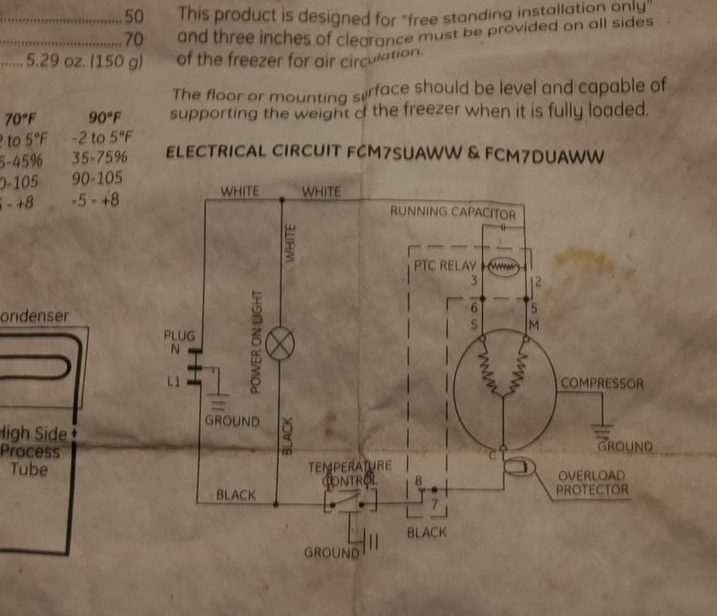
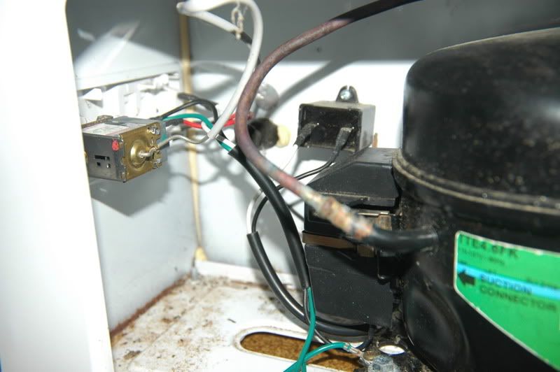
OK I've located a power diagram but I'm not sure if I'm interpreting it correctly. I'm attaching a pic of the diagram and a second pic showing the way I've got it connected. You can't see inside of the housing cover on the compressor so I'll just have to tell you how I've got it done...there are three blades on the PTC Relay which is mounted on the top two prongs on the compressor (posts # 5 & #6 on the diagram)...I've hooked one of the white leads from the power light splice on one of the two blades on "#5" side of the relay, the other blade below it I have the white lead from the capacitor attached to it. On the other side of the relay (#6) there is only one blade. I have the black lead from the running capacitor attached to it. Below this relay is a third prong on the compressor, (post "C" on the diagram) on which the overload protector is attached, I have the black lead from the temperature control attached to it. All the green grounds are secured to their positions at the base of the compressor, just out of view on the bottom picture. Am I good to go?  
|
|
|
|
|
|
Rank: Advanced Member
Groups: Senior Expert
Joined: 2/29/2008(UTC)
Posts: 19,638
Thanks: 1 times
Was thanked: 11 time(s) in 11 post(s)
|
It sounds to me that you have it hooked up correctly.
I cannot 100% guarantee it because I am not there. |
THIS FORUM IS DEAD!!!!!!! |
|
|
|
|
|
Rank: Member
Groups: Registered
Joined: 2/10/2011(UTC)
Posts: 8
|
Originally Posted by: denman  It sounds to me that you have it hooked up correctly.
I cannot 100% guarantee it because I am not there. I've plugged it in today and no arcs or sparks...the power on light is glowing, but mind you, I still have the unit turned off via the thermostat control. I'll turn it on tomorrow and hopefully the freezer will start...wish me luck!
|
|
|
|
|
|
Forum Jump
You can post new topics in this forum.
You can reply to topics in this forum.
You can delete your posts in this forum.
You can edit your posts in this forum.
You cannot create polls in this forum.
You can vote in polls in this forum.
Important Information:
The AppliancePartsPros.com uses cookies. By continuing to browse this site, you are agreeing to our use of cookies.
More Details
Close